Originally published in Microwave Journal Feb 12th 2021
MIKE GEEN – Chief Scientist – Filtronic
Along with low earth orbit (LEO) satellite constellations, high-altitude platform station (HAPS) systems—or high-altitude pseudo-satellites—operating in the stratosphere, have the potential to address the challenge of providing ubiquitous connectivity. Although there has been great progress in rolling out high speed mobile networks to serve major centers of population, terrestrial connections will never realistically cover every part of earth’s surface. To deliver the full promise of 5G and address the ‘digital divide,’ it is essential to provide coverage to low population areas where terrestrial mobile networks are not viable. This will be particularly important not only for improving personal communications, but also because many Internet of Things (IoT) sensors will need to be in these regions. This article gives an overview of the role of HAPS and satellites in forming “networks in the sky” and describes some of the RF challenges in designing the high data rate (10 Gbps-plus) communication links needed to backhaul data between earth and the satellite or HAPS, and between the platforms themselves.
CURRENT LANDSCAPE
Successive generations of mobile communications technologies have been effective in covering the most highly populated areas of the world, and modern life has come to depend on this ubiquitous connectivity. Mobile network operators in most developed countries have worked hard to meet their targets of connecting typically around 98 percent of the population in terms of where they live. However, the 5G goal of being able to connect everything —wherever it is on the planet—remains elusive for terrestrial mobile systems. A ‘digital divide’ has been created between populations who have a broadband connection, whether fixed or mobile, at an acceptable speed and those who do not. The FCC currently defines this benchmark as 25 Mbps, which places some rural parts of the U.S. on the wrong side of the divide. Furthermore, mobile platforms such as aircraft and ships, along with many IoT devices located in isolated areas, will most likely fall outside the range of terrestrial 5G telecommunications systems.
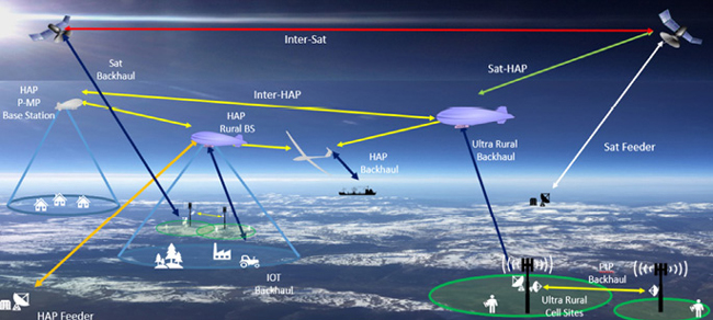
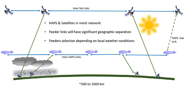
This ambition to connect everyone and everything, wherever they are located, therefore cannot be fulfilled by ground-based communication networks alone. Therefore HAPS, operating in the stratosphere at an altitude of around 20 km, along with constellations of LEO satellites at an altitude of between 350 and 1,100 km, are beginning to be deployed to help address the challenge of providing ubiquitous connectivity. A HAPS station comprises an unmanned aerial vehicle – which may be either a gas-filled balloon, an airship structure or a fixed wing aircraft—and a payload that is essentially a moving 5G base station with onboard solar panels or fuel cells to provide power. As the technology evolves, we can expect to see non-terrestrial networks being converged with terrestrial infrastructure, as shown in Figure 1. This introduces some interesting technical challenges in creating reliable links between each of the elements of these converged networks.
SPECTRUM ALLOCATIONS
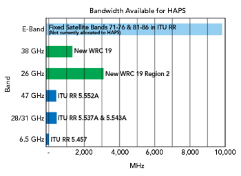
As demand for broadband capacity from these space and airborne systems grows, additional spectrum will be needed to support it. The telecommunications industry has successfully lobbied for more spectrum for HAPS, and the allocation of new wider bands around 26 and 38 GHz was agreed to during the 2019 World Radio Conference. In addition, experimental licenses were granted for E-Band (71 to 86 GHz), supporting the growing interest. Figure 2 summarizes the current and proposed bands, along with showing the geometry of the HAPS link to its ground station. There are commercial transceivers and high-power amplifiers available in these frequency ranges. Many have proven effective in XHaul (fronthaul, backhaul and midhaul) applications. Further development and qualification of these systems are exploited in the links that feed data between earth and the HAPS constellations.
While HAPS networks will mostly communicate directly with existing mobile phones, LEO satellite constellations will also generate the need for huge numbers of new fixed consumer terminals. As a result, this will create a demand for high volumes of components operating at frequencies up to 55 GHz where production volumes are historically low. The increase in manufacturing volume presents a challenge not only for OEMs but also for test equipment manufacturers. Simultaneously, it also offers new opportunities for companies who design and manufacture mmWave components and subsystems.
INDUSTRY INITIATIVES
The HAPS Alliance was formed in February 2020 with the aim of creating an ecosystem to promote the use of high-altitude stratospheric vehicles to extend connectivity to more people and locations worldwide. The alliance is based on an earlier initiative by HAPSMobile (a joint venture between Softbank and AeroVironment) and Alphabet’s Loon* to work together to advance the use of HAPS.
In addition to these companies who are developing the high-altitude platforms themselves, the alliance now counts among its members: telecommunications providers, including AT&T, Bharti Airtel, China Telecom, Intelsat, T-Mobile and Telefónica; aviation and aerospace companies like Airbus Defense and Space and Raven; and technology providers, including Ericsson, Nokia and Filtronic.
Further evidence of the growing interest in HAPS technology has been demonstrated by the formation of a Non-Terrestrial Connectivity Solutions project group within the Telecom Infra Project, an engineering-focused collaboration sponsored by Facebook.
HAPS USE CASES
There are several use cases for which HAPS technology is uniquely well suited, mostly related to their potential for extending enhanced mobile broadband to areas that are difficult to reach or not served by terrestrial mobile for economic reasons. These can include mountainous terrain, remote islands, marine regions and developing countries. A further application is mobile cell connectivity for passengers on board vessels or aircraft, or hybrid connectivity to reach passengers on board public transport vehicles like high speed trains, buses or river boats. They can also deliver fixed wireless access for users in isolated villages or remote industrial premises that cannot be reached by fiber.
Yet another use case is to supplement the capacity of existing networks to meet accelerating demand, and to supply “instant infrastructure” in emergency situations or for disaster relief. This can ensure network resilience for critical network links that require high availability. They can be rapidly deployed to cover a footprint of approximately 100 to 140 km diameter, over any type of terrain, requiring only minimal ground infrastructure.
HAPS can potentially be used to rapidly deliver media and entertainment content in multicast mode to RAN equipment at the network edge, to reduce latency for 5G cellular users, or in Direct-To-Node broadcast, whereby TV or multimedia services are delivered direct to home premises or to users on board a moving platform.
Utilizing their capacity rather than bandwidth, HAPS can be exploited for Massive Machine Type communications, to communicate with both local area and wide area IoT services.
SATELLITE AND HAPS SYNERGY
While it may appear that HAPS and LEO satellites both perform the same function, they are complementary. LEOs move rapidly in orbit relative to the earth so are more difficult to coordinate but have a wider area coverage. HAPS, being closer to the earth’s surface, are much easier and less costly to launch and deploy and give much lower latency. They feature “persistence”—the ability to remain stationary relative to the ground—and their transmissions are less affected by obstacles such as trees and buildings than terrestrial base stations. Unlike satellites, HAPS can be returned to earth for maintenance or payload re-configuration. They can quite literally be used as “base stations in the sky” providing additional capacity and wide cellular coverage in low density areas. They can also use the same frequency bands as terrestrial 3G, 4G or 5G networks, subject to regulatory approval, which means that the design of HAPS payloads should benefit from technology developments in 5G terrestrial base stations.
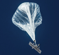
Experimental work with HAPS for communications relay has been taking place since the late 1960s,1 but it is only since the growth of mobile Internet that their commercialization has accelerated. There are some differences between the two types of HAPS. For example, the solar-powered unmanned aircraft manufactured by AeroVironment and deployed by HAPSMobile are heavier than air and can only carry relatively small payloads. Another, fuel cell-powered fixed wing platforms, like those from Stratospheric Platforms, are emerging, which can carry much larger payloads. Finally, the airship-style platforms, along with the balloon platforms being used by Loon, are lighter than air and can usually carry a heavier payload as shown in Figure 3. These airships have been deployed to extend mobile networks over some regions of Africa and South America. What the two styles of platforms have in common is the flexibility to be upgraded to newer technologies, and their multi-purpose capability, as they can be adapted for institutional, commercial communications or civil security applications. They are payload-agnostic and can readily be networked together and linked with other platforms.
HAPS LINK CHARACTERISTICS
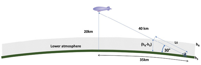
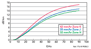
Breaking the converged network down into its individual elements, the characteristics that will be required for each of the links between them can be examined. Rain attenuation is one of the key factors to consider. Looking more closely at the HAPS feeder link geometry in Figure 2, for a platform at 20 km of altitude, the footprint can reach 70 to 80 km in diameter, and the link length will typically be about 40 km at an elevation of 30 degrees. Figure 4 shows the maximum rain attenuation per kilometer against frequency to permit 99.99 percent availability. For most of North America and Europe (Zone K), where rainfall is around 42 mm/hour, attenuation at 16 to 17 dB/km in E-Band is significantly higher than for the currently-used bands below 50 GHz. Nevertheless, as this service will be targeted at areas that have previously had no coverage at all, the demand for availability is likely to be lower than the 99.9 percent or 99.99 percent that is demanded of terrestrial networks, so some outage due to rain attenuation can be tolerated.
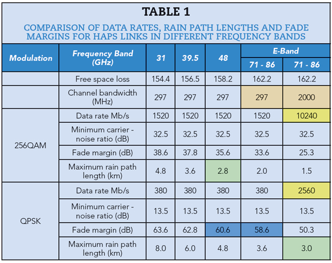
Potential data rates for HAPS feeder links in the different frequency band allocations are shown in Table 1, where they are compared for 256QAM and QPSK. Since antenna sizes are smaller at the higher frequencies, fade margins at 48 and 86 GHz are similar for the same antenna size and channel bandwidth. It is also striking that the data rate of over 10 GB/s that is available at E-Band using 256QAM is substantially higher than for the lower bands, due to the higher available channel bandwidth. Even if forced to drop back to QPSK to improve the fade margin, 2.5 GB/s data rate can still be achieved. The key figures for comparison are highlighted. Availability could be improved by combining E-Band with either 31 or 39.5 GHz.
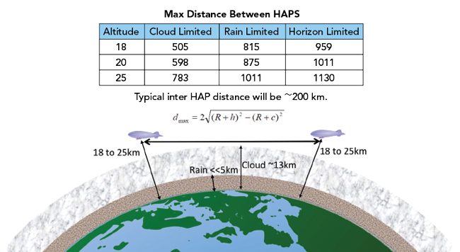
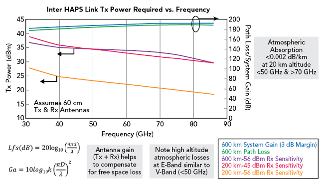
Figure 5 shows the formula for calculating the maximum distance between HAPS, showing the distances calculated for the different limitations. The distance normally used between HAPS is around 200 km. Rain and clouds have far less effect when the platforms are at this altitude, and the greatest limitation is the curvature of the earth’s surface. Figure 6 shows the transmitter power that would be required for inter-HAPS links in the different frequency bands, indicating that high-altitude atmospheric losses at E-Band are very similar to those in V-Band below 50 GHz. The higher antenna gain for a particular size helps to compensate for free space loss.
SATELLITE LINK LIMITATIONS
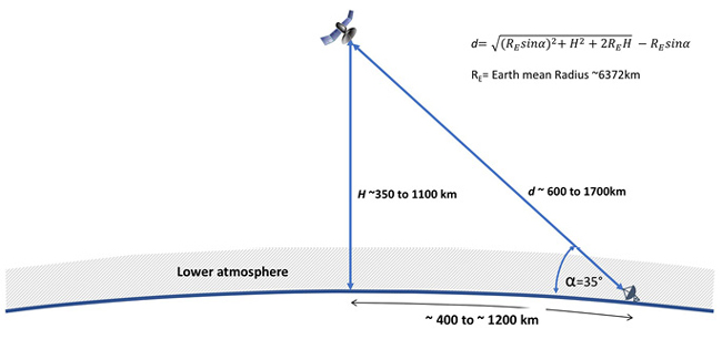
Performing a similar analysis of the limitations on the feeder links for LEO satellites, Figure 7 shows the bands available and the geometry calculations involved. The orbits being used for SpaceX satellites are in the range of 350 to 1,100 km, and with an elevation of 35 degrees at the earth station this gives a link path length of between 600 and 1,700 km. Free space losses now become much more significant in comparison to atmospheric losses, as a higher proportion of the path is above the atmosphere. The free space loss is several tens of dB higher than the figures for HAPS feeder links – around 195 dB for a 1,700 km link length at 86 GHz.
When this is translated into system requirements, system gains between 180 and 200 dB are viable for mmWave satellite feed links in clear weather conditions, and this is achievable in E-Band with antenna gains of less than 58 dBi (equivalent to a 1 m parabolic antenna) and transmit powers less than +40 dBm. However, rain is a severe issue that can limit availability in both E-Band and V-Band, where increases in system gain of between 20 and 40 dB would be required to ensure acceptable availability. Inter-satellite links have no atmospheric limitations and fewer horizon issues, so LEOs can be many hundreds of kilometers apart.
MMIC TECHNOLOGY AND ACTIVE ANTENNAS
Although many power amplifier technologies at microwave frequencies now use GaN technology for better efficiency and higher power, it is rare to find GaN devices that work in V- or E-Band. Some experimental GaN devices have shown promising results up to around 100 GHz, but have not been commercialized yet, and it is challenging to find commercially available GaN devices above 40 GHz. Also, although SiGe and CMOS devices can work at the higher frequencies, their power levels are low, and many more elements would be needed to reach the required EIRP of around +60 dBm.
While phased array and active antenna technology has proved effective at increasing the gain and EIRP of antennas, as well as providing beam-steering, as the frequency increases the half-wavelength dimension becomes smaller and they become difficult to fabricate. Increasing the number of elements also increases power consumption, so using high-power GaAs devices with fewer elements has become the optimum solution for E-Band links.
E-BAND TRANSCEIVER TECHNOLOGY
Figure 9 shows a typical payload for a satellite or HAPS. As well as the eNodeB (LTE) or gNodeB (5G) base station, there are transceivers for the inter-platform links and the ground link, meaning that each platform would require three links at Ka-, V- or E-Band.
Figure 10 shows a block diagram of the basic transceiver that is being used for these E-Band links. It is fully integrated, for use in the 71 to 76 GHz and 81 to 86 GHz bands. It gives a highly linear transmitter output of more than 20 dBm and supports 256QAM modulation and above, along with a channel bandwidth more than 2 GHz. Phase noise is typically -112 dBc/Hz at 1 MHz. An integrated diplexer facilitates a single T/R port for the antenna interface, and there is also a single 50-way connector that supplies all communication between the module and the modem, as well as DC power, baseband data and control signals. A small, lightweight form factor is required, due to the number of elements to be accommodated and to optimize the overall weight of the payload. Morpheus II transceivers have a footprint of 90 × 80 mm and weigh only 110 g. For higher power levels, power combined amplifiers can be used – for example the Filtronic E-Band Cerus power amplifier can deliver output powers greater than 2 W. Figure 11 shows an example transceiver module, which is being used in E-Band links for terrestrial applications and has also been customized for HAPS/LEO links.
CONCLUSION
Global mobile data usage is growing rapidly, and the new use cases enabled by 5G will create demand in areas that are underserved – and difficult to serve – by terrestrial cellular networks, such as more remote and sparsely-populated regions. Terrestrial networks will not be able to provide 100 percent coverage, and this creates a clear case for converged networks that will integrate satellites and HAPS with terrestrial mobile networks. Although hybrid satellite solutions are not expected before 2023 to 2024, the standardization work for integration of the satellite in 5G networks is underway. Following the finalization of 3GPP Release 16 at the end of 2019, it is expected that provisions for satellite and HAPS systems could form part of Release 17. Since spectrum is limited and is subject to many conflicting and sometimes overlapping demands, mmWave frequency bands are expected to form a key part of the solution for the links between satellites, HAPS and earth terminals. The FCC has approved several trials in V-, E- and W-Bands, confirming the growing role for mmWave bands in the future.
While the use of mmWave bands presents some technological challenges for semiconductor devices, RF systems, antennas and network architectures, some long range mmWave transceiver solutions with high data rates up to 40 Gb/s and above have been developed and successfully demonstrated in trial systems and will improve for future systems.
For more information on this material, visit YouTube at https://youtu.be/bDGmkIF4-no.